12 Volt Ignition Coil Wiring Diagram : Electronic Ignition Coil Wiring Diagram Powerspark Ignition Blog The Leading Supplier Of Classic Car Electronic Ignition Systems : This page links directly to all of my 6 volt and 12 volt wiring diagrams.
12 Volt Ignition Coil Wiring Diagram : Electronic Ignition Coil Wiring Diagram Powerspark Ignition Blog The Leading Supplier Of Classic Car Electronic Ignition Systems : This page links directly to all of my 6 volt and 12 volt wiring diagrams.. I also have the wiring diagram for a key start 12 volt generator tractor; With the ignitor electronic ignition the ignition switch wire will no longer be connected to the coil. Both are 12 volts hot! This page links directly to all of my 6 volt and 12 volt wiring diagrams. See chart on back page for coil recommendations.
Just scroll down and click on the link to the specific wiring diagrams you are looking for. The big red lug (10 gauge wire) at the back is 12 volt output, goes directly to the starter solenoid battery cable terminal via a proper fuse link or maxi fuse. When you make use of your finger or the actual circuit along with your eyes, it may be easy to mistrace the circuit. But i don't have anything for a key start 12 volt alternator conversion. There'll be main lines which are represented by l1, l2, l3, and so on.
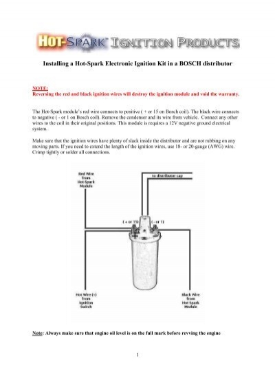
Installing A Hot Spark Electronic Ignition Kit In A Bosch Distributor from www.yumpu.com 1997 1998 1999 46l ford f150 f250. This video concentrates on coils from an electronic point of view and reading wiring diagrams. Engine fe290 engine ignition components and flywheel. Architectural wiring diagrams perform the approximate locations and interconnections of receptacles, lighting, and surviving electrical facilities in a building. There'll be main lines which are represented by l1, l2, l3, and so on. Ford 8n wiring diagram 12 volt site resource. Attach the ignitor red wire to the ignition side of resistance, or any 12 volt ignition power source. Injunction of 2 wires is usually indicated by black dot at the intersection of two lines.
I also have the wiring diagram for a key start 12 volt generator tractor;
You can find the 1992 1993 ignition system wiring diagram here. This page links directly to all of my 6 volt and 12 volt wiring diagrams. This procedure is likely the same for the 1984 85 carts as well so i included them in the thread title. Published by means of tops stars team on december, 7 2013. 9 connect the black wire from the transistor box to the negative on the second coil (see wiring diagram).remove the outer protective sleeve and cut the wire to required length. The simple fix for this is to reverse the two primary wire connections on the ignition coil. Accuspark wiring diagrams 1929 a 6v to 12v diagram vw electronic distributor 1973 evinrude ignition switch 12 volt coil generator boyer bransden mkiii ford 9n 2n tractor conversion manualzz bosch alternator farmall cub help you understand converting one wire beedsd for how motorcycle basic case 6 free vincent electrics 8n oliver 60 system circuit. Otherwise, the arrangement won't work as it should be. 12 v dyna coils, wiring diagram & mounting kit all prices listed are current as of 07/13/21. But, it does not mean connection between the wires. To ignition switch red wire bla ck wire resistance wire b allast resist or the ignitor can also be installed in applications retaining the ballast resistor or resistance wire. Attach the red ignitor wire to the positive coil terminal. Thanks don, but i actually have that wiring diagram.
See chart on back page for coil recommendations. 12 v dyna coils, wiring diagram & mounting kit all prices listed are current as of 07/13/21. Engine fe290 engine ignition components and flywheel. 2,3 and 4 wire coil versions are different in Accuspark wiring diagrams 1929 a 6v to 12v diagram vw electronic distributor 1973 evinrude ignition switch 12 volt coil generator boyer bransden mkiii ford 9n 2n tractor conversion manualzz bosch alternator farmall cub help you understand converting one wire beedsd for how motorcycle basic case 6 free vincent electrics 8n oliver 60 system circuit.
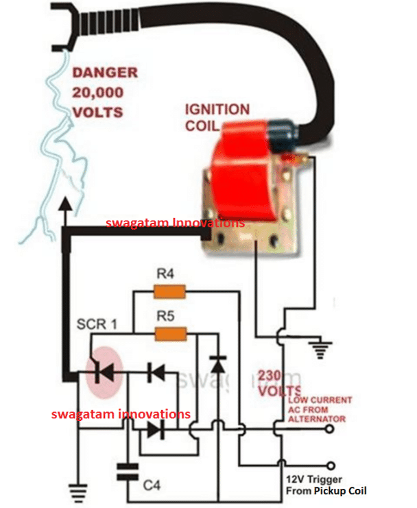
Simple Capacitive Discharge Ignition Cdi Circuit Homemade Circuit Projects from www.homemade-circuits.com Remove the ignition switch wire from the negative coil terminal. The negative port of ignition gives the signal voltage to tachometer so how much ohm the resistance between the negative port and ground? This video concentrates on coils from an electronic point of view and reading wiring diagrams. But, it does not mean connection between the wires. Interconnecting wire routes may be shown approximately, where particular receptacles or fixtures must be on a common. This procedure is likely the same for the 1984 85 carts as well so i included them in the thread title. Coil beim führenden marktplatz für gebrauchtmaschinen kaufen. This is how you can test the ignition.
You can find the 1992 1993 ignition system wiring diagram here.
12 v dyna coils, wiring diagram & mounting kit all prices listed are current as of 07/13/21. There'll be main lines which are represented by l1, l2, l3, and so on. New version, hopefully better explained. Home 2000 2005 carryall 1 2 6 by club car engine fe290 engine ignition components and flywheel. Published by means of tops stars team on december, 7 2013. The wire running from the ignition switch to the coil, will need to be cut and a ballast resistor put in line. The negative port of ignition gives the signal voltage to tachometer so how much ohm the resistance between the negative port and ground? Each part should be placed and connected with different parts in particular manner. Ignition coils of this type are usually a little larger than a soda can and are heavy. Farmall h 12 volt conversion wiring diagram along with international tractor wiring diagram also ford 8n alternator diagram as well as wiring lights diagram for international dt series further farmall h ignition system together with also cadillac 6 volt positive ground wiring diagram together with h wiring. Attach the red ignitor wire to the positive coil terminal. These coils had very simple wiring. Ford 8n wiring diagram 12 volt site resource.
As stated earlier, the traces at a 8n ford tractor wiring diagram 12 volt signifies wires. Architectural wiring diagrams perform the approximate locations and interconnections of receptacles, lighting, and surviving electrical facilities in a building. I also have the wiring diagram for a key start 12 volt generator tractor; Published by means of tops stars team on december, 7 2013. 12 v dyna coils, wiring diagram & mounting kit all prices listed are current as of 07/13/21.
Coil Wiring Hook Up S Itinerant Air Cooled from i187.photobucket.com Jetzt eine riesige auswahl an gebrauchtmaschinen von zertifizierten händlern entdecken Just scroll down and click on the link to the specific wiring diagrams you are looking for. Published by means of tops stars team on december, 7 2013. There'll be main lines which are represented by l1, l2, l3, and so on. This page links directly to all of my 6 volt and 12 volt wiring diagrams. When you make use of your finger or the actual circuit along with your eyes, it may be easy to mistrace the circuit. Ford 8n wiring diagram 12 volt site resource. September 3, 2019 at 11:08 pm.
The negative port of ignition gives the signal voltage to tachometer so how much ohm the resistance between the negative port and ground?
This procedure is likely the same for the 1984 85 carts as well so i included them in the thread title. 1997 1998 1999 46l ford f150 f250. Because the output spark is very much higher voltage (20,000v) than the car battery (12v), it doesn't care if the battery polarity is helping or hindering by a meager 12 to 14 volts in battery potential. Both are 12 volts hot! Home 2000 2005 carryall 1 2 6 by club car engine fe290 engine ignition components and flywheel. This video concentrates on coils from an electronic point of view and reading wiring diagrams. Attach the black ignitor wire to the negative coil terminal. The smaller red wire on the side plug, (14 gauge) is the regulator excite wire for the internal regulator. This is how you can test the ignition. But i don't have anything for a key start 12 volt alternator conversion. The big red lug (10 gauge wire) at the back is 12 volt output, goes directly to the starter solenoid battery cable terminal via a proper fuse link or maxi fuse. Attach the ignitor red wire to the ignition side of resistance, or any 12 volt ignition. 2,3 and 4 wire coil versions are different in
Attach the ignitor red wire to the ignition side of resistance, or any 12 volt ignition ignition coil wiring diagram. New version, hopefully better explained.


0 Komentar